
 Case in point: nixie tubes. They were developed in the fifties and were one of the first technologies for electronics to display numerals. They’re totally obsolete. Their job is done much better and more easily by LCDs, OLEDs, and the like. Despite this, they’ve become pretty popular among electronics nerds. They’re kind of a litmus test. Some people hate them and think they’re pointless, others love them despite their obvious pointlessness. I am firmly in the latter group. They haven’t been manufactured in the US for decades, but you can still get them from the former Soviet Union. I recently got 6 from a nice guy in Chelyabinsk.
The problem with nixies (and one of the reasons nobody uses them anymore) is that they require high voltages, around 180V DC. So I need a power supply that can source 180V. It also needs to be able to supply about 2.5 milliamps. This is a problem because there aren’t many power supplies available that output 180V, and those that are available need 9-12V.
 I don’t have a 9-12V power supply, but I have a ton of USB wall warts that output 5V. So I like to power my projects with them when possible. This means I need to learn to make my own power supply! One that will step 5V from a USB supply up to 180V.
Enter the MC34063, a controller for switch mode power supplies. It’s been around for a long time, so it’s easy to find them used in other people’s projects. This allowed me to learn to build my own regulator to step the voltage from one of my USB supplies to power my Nixies!
The Regulator Circuit
Getting 180V from a USB wall wart is, to say the least, difficult. The datasheet for the MC34063 is very helpful, but the example circuits it presents won’t step 5V to 180. The best I could get from the circuit in figure 9 of the datasheet was around 75V.
Part of the problem is that the MC34063 can’t switch fast enough. This can be fixed by using the “ratio extender” circuit described in figure 19 of the application note for the MC34063. Too bad that only got me up to around 85V. And using an external current boost transistor as in figure 10 of the datasheet only pushed it up to 90V.
Luckily, this guy’s website is super helpful. He presents a great design for a high voltage power supply based on an MC34063 and I managed to adapt his circuit for my purposes. See below for the breadboard layout and schematic. The red wire on the right of the board is for Vin and the red wire on the left is the 180V output.

breadboard layout for 180V power supply for nixie tubes
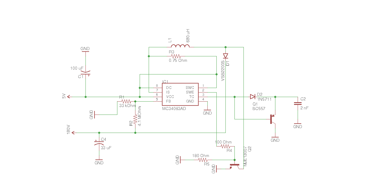
180V power supply for nixie tubes
The Nixie Circuit
The breadboard layout below allows an Arduino to control a single nixie tube using a K155ID1 nixie controller. The K155ID1 takes input from 4 I/O pins on the Arduino. It interprets the high/low signals as a 4 bit binary number. For example, if the signal from the Arduino is LOW, LOW, HIGH, LOW, or 0010 the controller grounds the “2” cathode, which causes it to glow. Be careful when wiring this up because the ordering of the pins on the K155ID1 is not logical. And the way the chip interprets its inputs is also not logical. Check the datasheet.
Notice the red wire leading off to the right of the image. That’s the +180V wire from the power supply. I’m going to skip example code for a single nixie. If you really need code for a single nixie it can be adapted from the code for the multiplexed setup below.
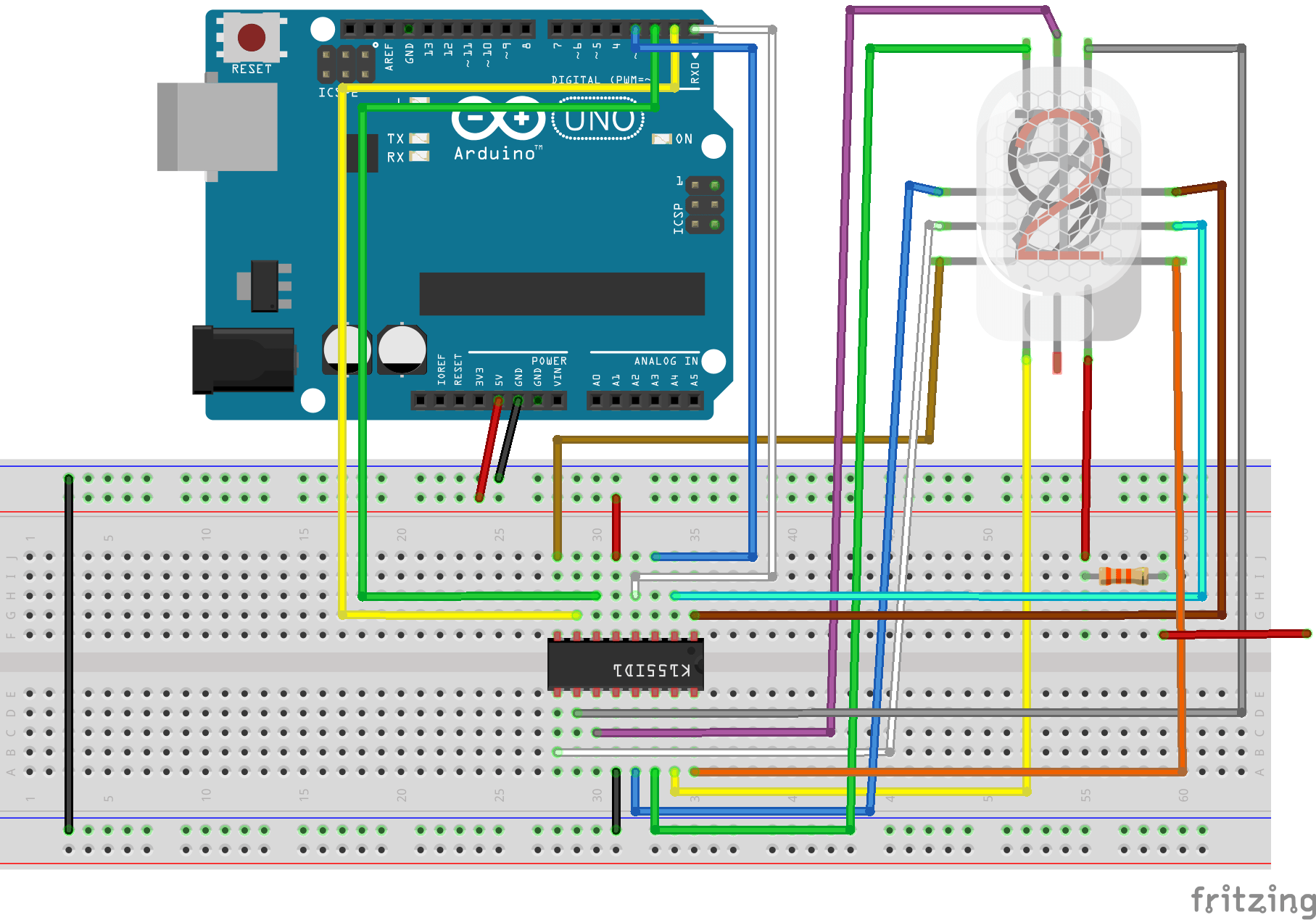
control circuit for a single nixie
Controlling Multiple Nixies
The way I’ve chosen to control multiple nixie tubes is through multiplexing. This means the cathodes of the nixie tubes are wired in parallel to the same K155ID1 controller chip. The anodes are switched on and off by the Arduino via discrete transistors. The Arduino alternately switches the anodes of each tube on every 5 milliseconds making each tube flash alternately. Even though the tubes are actually flashing, persistence of vision makes them appear to be steadily lit.
It is possible to drive multiple nixie tubes without multiplexing, but multiplexing provides a couple of important advantages. First, without multiplexing, each additional tube requires its own K155ID1 controller IC and 4 additional pins on the Arduino. Multiplexing means we only need 1 controller IC for all of the tubes, and additional tubes only require 1 additional pin.
Second without multiplexing, the current required from the nixie power supply is equal to the current required for a single tube multiplied by the number of tubes. The required current for multiplexed tubes is equal to the current for a single tube. That means the current required from the power supply for multiplexed tubes is much lower. This is good because I really don’t want to push the limits of the power supply I built.
Multiplexing requires a little extra complexity in the code and it makes the tubes appear a little bit dimmer, but I think those costs are worth the benefits.
The breadboard layout below is, admittedly, a hot mess. It somehow looks better on an actual breadboard. It does, however, allow for multiplexed control of multiple nixie tubes. Note that the PNP is an MPSA92 and the NPN is an MPSA42. Note also that the red wire running off to the right of the breadboard is for the 180V input.
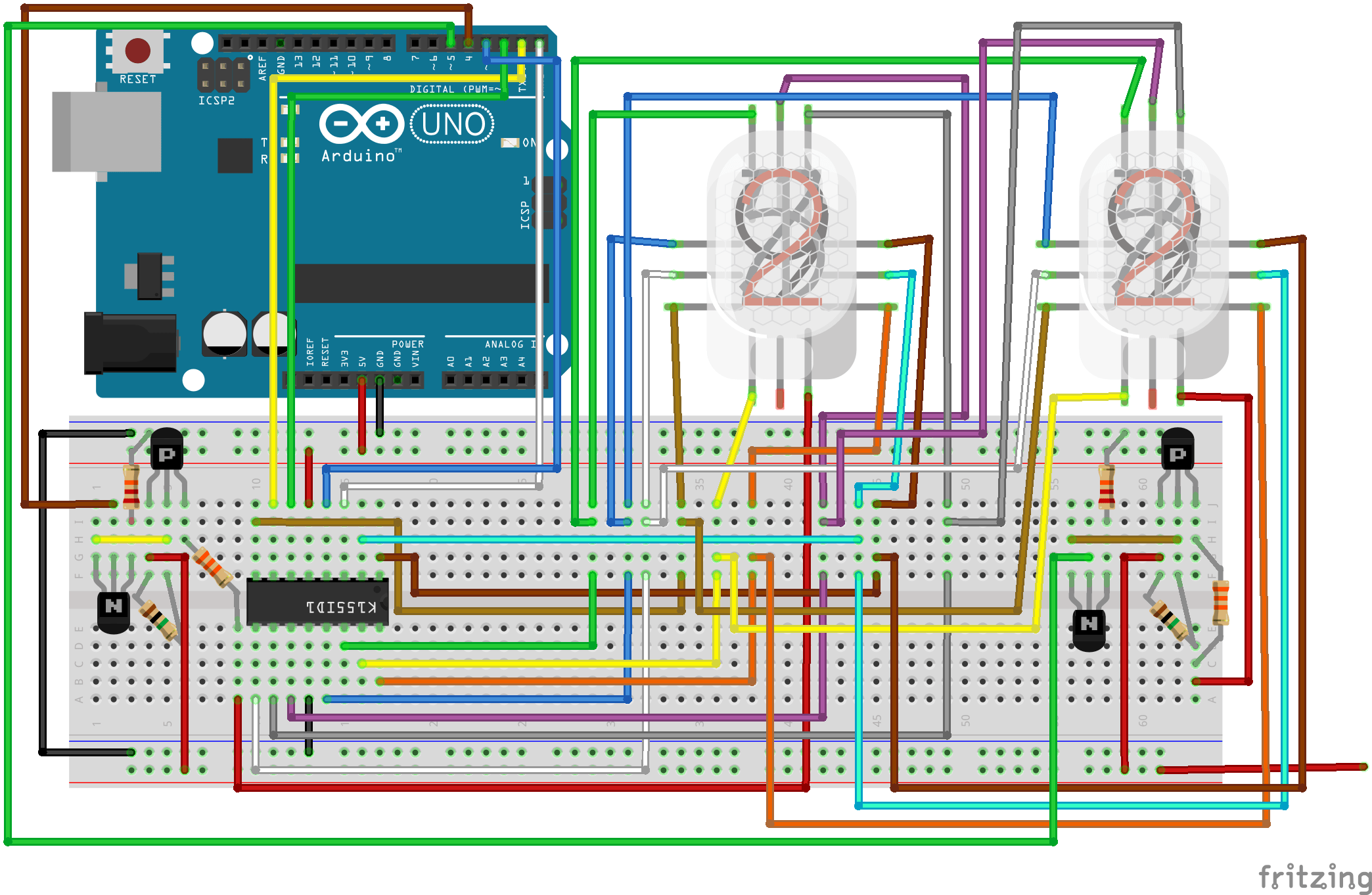
breadboard layout for multiplexed nixies
Example Code
The code below displays a count on the two multiplexed nixies in the breadboard layout above. The two tubes count from 00 to 99, incrementing the count every half second. The count resets to 00 once it hits 99.
const uint8_t numTubes = 2;
const uint8_t tubes[numTubes] = {4, 5};
const uint8_t numbers[10][4] = { {0, 0, 0, 0},  // 0
                                 {0, 0, 0, 1},  // 1
                                 {0, 0, 1, 0},  // 2
                                 {0, 0, 1, 1},  // 3
                                 {0, 1, 0, 0},  // 4
                                 {0, 1, 0, 1},  // 5
                                 {0, 1, 1, 0},  // 6
                                 {0, 1, 1, 1},  // 7
                                 {1, 0, 0, 0},  // 8
                                 {1, 0, 0, 1}}; // 9};

uint8_t curTube, curNum;
long tubeSwitchTime, numSwitchTime;
uint8_t digits[numTubes] = {0, 0};

void setup()
{
  for (int i = 0; i < 6; i++)
    pinMode(i, OUTPUT);
  curTube = 0;
  curNum = 0;
  tubeSwitchTime = millis();
  numSwitchTime = millis();
}

void loop()
{
  long curTime = millis();
  if (curTime - numSwitchTime > 500)
  {
    numSwitchTime = curTime;
    curNum++;
    curNum = curNum % (uint8_t)pow(10, numTubes);
    for (int i = 0; i < numTubes; i++)
    {
      digits[i] = curNum / pow(10, i);
      digits[i] = digits[i] % 10;
    }
  }
  if (curTime - tubeSwitchTime > 5)
  {
    tubeSwitchTime = curTime;
    digitalWrite(tubes[curTube], LOW);
    curTube++;
    curTube = curTube % numTubes;
    for (int i = 0; i < 4; i++)
    {
      digitalWrite(i, numbers[digits[curTube]][i]);
    }
    digitalWrite(tubes[curTube], HIGH);
  }
}
If you did everything right, your nixies should look like this:
